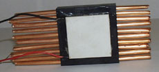
 In this image you can see the 40mm (1.57") square peltier junction. This peltier draws 3.9
amps and can pump a maximum of 33.4 Watts. The heatsink is 2.3" square and has 10 fins.
NOTE: You can click on the images to get (slightly) bigger versions.
 In this image you can see the 40mm (1.57") square peltier junction. This peltier draws 3.9
amps and can pump a maximum of 33.4 Watts. The heatsink is 2.3" square and has 10 fins.
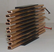 Don't laugh! The best copper tubing I could get my hands on was quarter inch (0.25). The
space between the fins is roughly one fifth of an inch (0.20) so I had to hammer the tubes
to fit. The copper tubes were held in place by silicon gell.
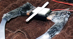 It took a lot of silicon gell to get the unit semi water tight. I never got it totally
water tight but it was close enough to do some experiments. I placed a copper tube on the
top of the cold plate of the peltier. In a short period of time both the peltier and the
copper tube were getting covered in ice.
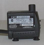 My handy little $20 60gph submersable pump from Home Depot. Thanks Michael for the
recomendation (www.agaweb.com/coolcpu). I was a little
nervious about throwing this thing in a bucket of water and then plugging the cord in to the
wall AC.
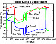 Here are the results of this unit in action. Temperatures were recorded in two places and
in 10 second intervals. I had a sensor on the cold plate of the peltier (blue line) and in
the bucket (red line). I computed the temperature delta and ploted it in green. You can see
from the graph that the ice buildup acted as an insulator which prevented the peltier from
reaching a lower temperature. When I place a sheet of foam over the cold plate I got an
instant 20 degree drop in temperature.